few hours with… Elegoo/ Arduino (no prior experience with microcontrollers)
I recently bought “The Most Complete Starter Kit Mega 2560 Project” and decided to record my progress. I have some hobby level experience in programming iOS apps in Swift language but never done anything with microcontrollers before. I have watched some videos on Youtube and most of the time look like they have done it all life and just showing how it’s done. So let’s see how hard it is….
Elegoo Uno works the same as the Arduino brand. It’s just not the official “Name Brand”. It’s like Arduinos clone, uses Arduinos open-source software and drivers but is a little bit cheaper. I have no previous experience in any kind of microcontroller’s and reviews were not bad so I bought Elegoo.
So let’s start with preparations. In the starter kit, there is a CD, and if you use a laptop same as me then there is a very big possibility that you don’t have a CD reader. That is not a big problem because on CD you will find a link where the tutorial download is located.
There are a lot of different files to download so you need to find the correct one in my case it is “Elegoo Mega 2560 The Most Complete Starter Kit”. Download it, unzip, and inside the open folder “English” and after that find file “The Most Complete Starter Kit for MEGA V1.0.19.09.17.pdf”. You can read all the intro and then let’s start with lesson 0”.
You can read through my experience or you can join by buying your own starter kit. You can find this starter kit in my affiliate link here.
Lesson 0 Installing IDE & Lesson 1 Add Libraries and Open Serial Monitor
Instruction is very easy to understand and no problems were installing it. Instructions were so detailed and well explained for every type of computer that I scrolled so fast and actually missed Lesson 1 where they show how to add libraries. Just in the first project where the library was necessary, I saw the reference to Lesson 1.
IDE — Integrated Development Environment, basically software in which will be written code for the microcontroller, in this case, it’s “Arduino”.
Lesson 2 Blink

This is practically just plugging in the Mega 2560 controller board and with few lines of code, you can blink the led light which is located on the controller board. There is basically no effort but it was fun because it’s the first time when you can send instructions to this controller board and now you know that it works.
Basically 5 easy steps:
- Plug-in USB cable to Mega 2560 controller board and computer
- Open Arduino software
- Go to File/ Examples/ 01.Basics/Blink
- Press arrow to right (“Upload”) to send the command to the microcontroller
- Change “delay” time to a smaller value so you can see how it’s blink faster because you said so.
Lesson 3/4 LED
In this project, you will turn on a red LED light. In the tutorial book, there is some general information about the components you will use in this and a lot of other projects.
The first component is the breadboard. A very awesome component that will save a lot of time. Everything can be connected without solder, it’s perfect for this kind of beginner's projects and prototyping. When you look at the breadboard and tools in the starter kit, even if you don’t understand how it works, you can have some ideas on how it’s gonna be used but when you get to a monster called “resistor” things are getting harder.
This far I understand that LED cannot handle power from battery or voltage, so you need a resistor. A resistor will resist the flow of electricity. The bigger value of the resistor more electricity is resisted and the LED light will become dimmer.
Connecting everything is very easy and everything works just fine, but the last sentence of instruction made me ask a few questions. So the last sentence is “It does not matter which side of the LED we put the resistor, as long as it is there somewhere”. So why does it not matters? The reason probably is breadboard and how it works…. but how a breadboard is really working?
So more about breadboards — as I wrote before they are used for prototyping. The reason why it does not matter on which side is resistor — on breadboard five vertical holes are connected together (see picture below).
If you wanna know more here are some links:
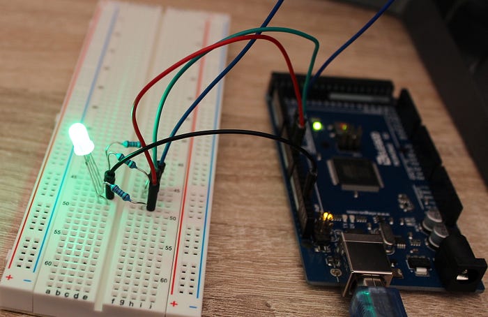
Few next lessons are basically an introduction to all the awesome gadgets that are located in the starter kit. You can see how RGB LED light work in lesson 4.
In lesson 5 (Lesson 5 Digital Inputs) you are introduced to the first gadget you can interfere with — buttons. In instruction there was this picture:

The button looks quite large but in reality, it’s quite small. I look through a starter kit 2 times when I found it where I was not expecting — together with small details as LED and other small stuff.
Lesson 6 and 7 is about buzzers…. active and passive buzzers. They buzz… Okay, let’s go to the next lessons.

So next lesson 8 is an introduction to “Tilt Ball Switch”. It’s actually quite an amazing thing — it can detect orientation or inclination. They are not as precise or flexible as an accelerometer but they have their advantages — they are inexpensive, low power, easy to use and big ones can switch power on their own. And let’s be real — not for every project you need high precision.

Lesson 9 Servo — a geared motor that can rotate 180 degrees. Probably useful for some projects where you need a switch or other limited rotation.

Lesson 10 Ultrasonic Sensor Module. This actually surprised me a lot. When I was unboxing and just looking at each gadget I took this in hands for a few seconds and thought — ou loudspeaker — and put back in the box. When I started to read instructions — distance measurements…. what. It’s actually an ultrasonic sensor module that can make measurements from 2cm to 400cm with a non-contact measurement function. Amazing. It uses a high-level signal and detects when the signal bounces and comes back.
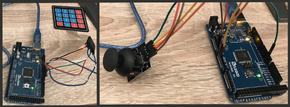
Few next lessons are introductions for keypads (Lesson 11 Membrane Switch Module), temperature/ humidity sensor (Lesson 12 DHT11 Temperature and Humidity Sensor ), analog joystick (Lesson 13 Analog Joystick Module). All are interesting projects where you can learn the basics of how they are connecting to the microcontroller, how you can program them, and what are some important data about them. If you will not continue with Elegoo/ Arduino projects in the future then after all projects will be finished, you can probably make your own thermometer.
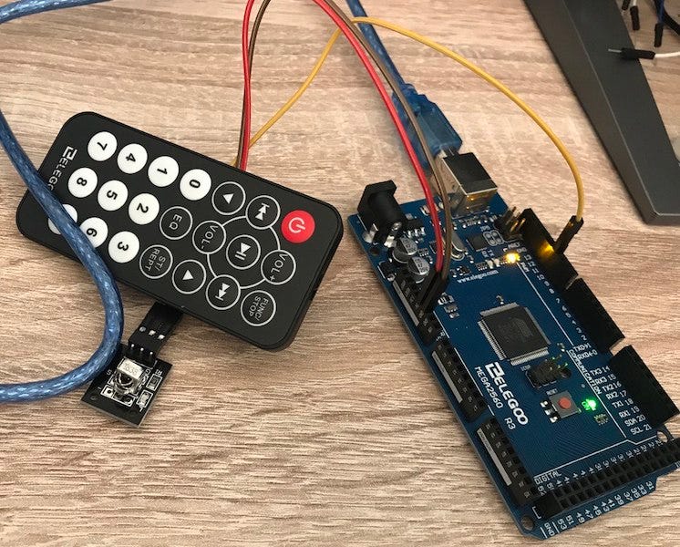
The next project was about the IR receiver (Lesson 14 IR Receiver Module). The starter kit provides you with a receiver sensor and remote control. This was quite exciting because I already knew where I would use this kind of sensor and remote. It is another project where I plan to use a stepper motor and IR receiver for controlling it.

So the next project was — Lesson 15 MAX7219 LED Dot Matrix Module. You probably have seen signs, clocks, and other stuff made with this, but I had no idea that it’s quite easy to set it up if you have all components…. I assume it’s quite easy because here we can work with an 8x8 LED matrix module, probably with bigger ones there is much more work.
When you upload code to a microcontroller LED matrix module will do a lot of blinkings, but here I wanted to play a little bit with code to get a result of my own. So with very primitive code, I made “Hi” text. I just found how each LED is lit up and turned on those who make the text appear.

Lesson 16 GY-521 Module — from the name and how this small chip looks I would never guess what it can do. It’s an accelerometer and a gyro combined in one small chip. You could find them in smartphones, smartwatches, game controllers, etc. For example, when it’s built-in phone it can detect phone orientation. Accelerometer — in short version — inside chip there is a box and inside the box, there is a ball. When the ball touches one of the box walls chip can detect which wall is touched and send information to the microcontroller. And gyro works….on the principle of Coriolis acceleration. From the text in the manual, I could not quite understand so I found this video. I could try to explain but better see this video here.
Few next projects are introductions to some other cool stuff like movement sensors (Lesson 17 HC-SR501 PIR Sensor), the water level sensors (Lesson 18 Water Level Detection Sensor Module), realtime clock module (Lesson 19 Real-Time Clock Module), sound sensor (Lesson 20 Sound Sensor Module) and card reader module (Lesson 21 RC522 RFID Module). All are very interesting stuff and if your imagination works, there are a lot of fun projects to make.

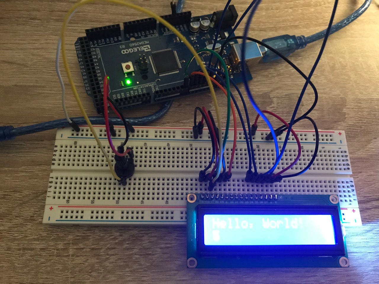
The next project was a small struggle — Lesson 22 LCD Display. I was putting all together from instruction as usual. When attached to a laptop and installed code to the microcontroller display background was lighting up but nothing was showing on the screen. I recheck everything a few times and could not make it show a message on the screen. This was the first time I did not finish the project and left it there for the next day to start over. The next day I was going through instructions one more time and I carefully examined the image in instructions and…. potentiometer in instructions looked quite different from mine. It had some screwing part on it and mine was flat…. I checked the starter kit one more time and found separate detail — the screwing part for the potentiometer. This was a good lesson because after reading instruction one more time carefully from start till the end I found text — make sure the backlight is lit up, and adjust the potentiometer all the way around until you see the text message. I was so excited to see the text on display that after wiring I did not read instruction till the end…
After this project next was upgrading this LCD screen to a thermometer (Lesson 23 Thermometer). When I was preparing for this project I thought it will require a temperature and humidity sensor from the previous project but no. In this project, the temperature is measured with a thermistor — a resistor that changes its resistance with temperature. Technically, all resistors are thermistors but they are not so sensible as this particular thermistor. If someone showed me this thermistor and asked what it does I could not guess in a million years — it is small… very small. It is a few times smallest than a resistor.
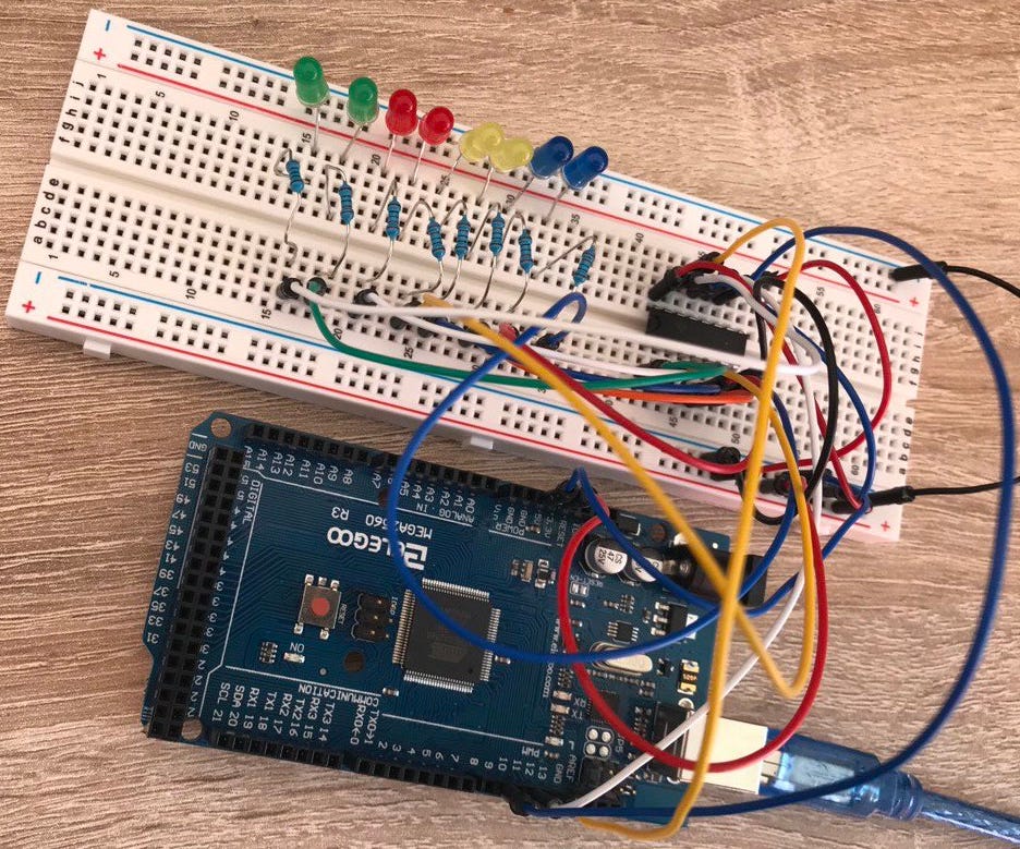
After this came three projects which were one larger project split into three parts. Lesson 24 Eight LED with 74HC595. The first part was making eight led light strip with a chip called 74HC595…. one more time — chip called 74HC595. Why I writing this two times because this can be a reason for the struggle. Long story short I did not finish this project as fast as I wanted because in the starter kit two chips look like identical twins but they are different… very different. When finally I found out my stupid mistake, I made it right and finally could enjoy the project. This chip helps with wiring, so you don’t have to wire all eight led light to a microcontroller. If all led’s need to be lighting at the same time wiring could look different but in this three-part project, it was important to light each led light separately so more messy wiring if a chip was not available.
Now when this was ready next par was about a serial monitor (Lesson 25 The Serial Monitor). A serial monitor is part of Arduino software. When coding your microcontroller in this serial monitor you can receive information from and send it to a microcontroller. In this project with the help of a serial monitor and previously wired microcontroller, you can turn on/ off each light separately. So it’s not very useful to manually turn on/off something from your laptop, but actually, it’s more for testing purposes, you can simulate data received from and sent to the microcontroller.
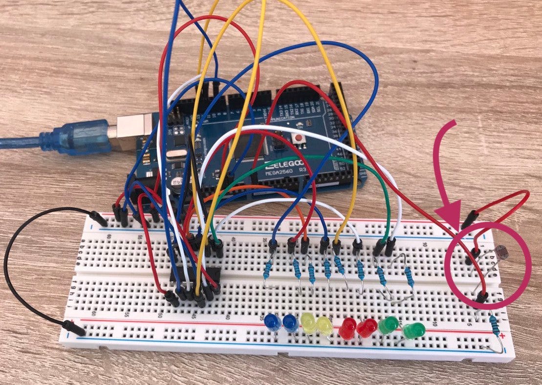
And the third part is to add one more element to a previously wired microcontroller — Lesson 26 Photocell. Additionally, you will add photocell — one more cool resistor type, and this time it’s a light-dependent resistor. It can sense how much light is “ falling” on it. The code was made so more light sensor gets more led light was on. But for me, it felt quite the opposite. For me was more logical — less light it will get more led light should light up, so that’s what I did. I studied code trying to understand what is done and what could I do. It was more like a math problem than a coding problem. But in the end, I reversed it.
Next to projects is with segment displays first with one seven-segment display (Lesson 27 74HC595 and Segment Display) and second with four seven-segment displays built-in one-piece (Lesson 28 Four Digital Seven SegmentDisplay). One seven-segment display can show numbers from 0 to 9. It can show also a dot in the right bottom corner but it does not count as a segment. In these projects, you will use the 74HC595 chip again and this time no mistakes… A lot of wiring must be done before counting from 9 to 0 begins. Important note — when you will show this to a family member or friend remember — when acting that you are disposing of an exploding object — check which wire to pull out so you don’t look dumb ;).

Interesting fact — in the end, one display took a little bit more wiring than four displays. Probably not so interesting fact if you have a lot of year experience with microcontrollers but I assume for those people not much can be an interesting fact cause they are working with quite amazing stuff.
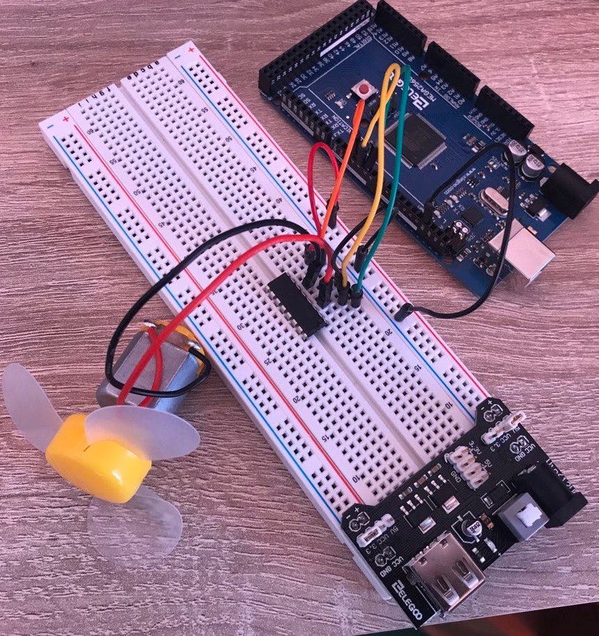
Now next lesson was again exciting for me — motor (Lesson 29 DC Motors). From time to time in my head, there were ideas that it would be cool to add a motor to that or this. It always felt quite impossible to learn how to control a motor in a way I need it. So when I saw the motor in a starter kit I wanted to get my hands on it. In this project, you will be building a fan with a small DC motor. The motor requires more power than the previous projects so here you will be introduced to a power supply module. So you will connect this module to the breadboard and attach it to the adapter. The module has a turn on/ off switch on it — don’t forget to push it. The next important part of this project is a chip named L293D IC. Again — read the name on the chip correctly, this was a chip that I accidentally tried to use in another project. They look the same but do quite different things. This chip does a lot of work so wiring is very easy. The most important thing here — don’t try to connect a motor directly to the microcontroller board because there is a high chance you will damage the microcontroller. So when everything is plugged, wired and code uploaded to the microcontroller you can start testing how the motor is working.
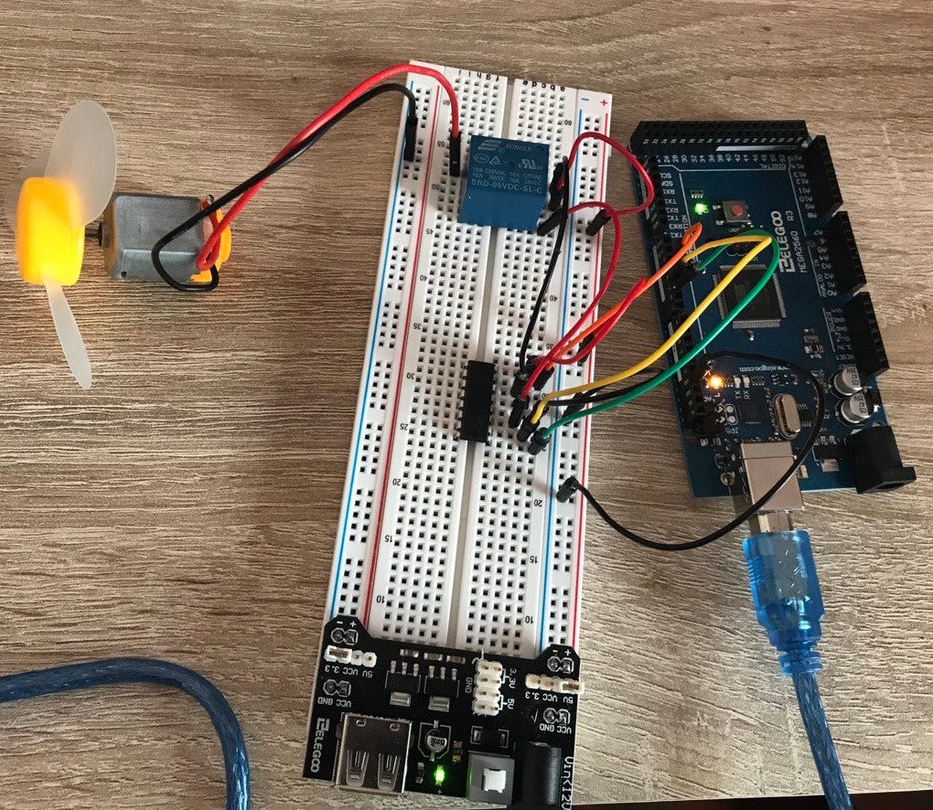
The next project is about relay (Lesson 30 Relay). Using the same motor from the previous project you will learn how to use relay… maybe not learn how to use it, but you will see that putting it in according to instructions motor will work. Realy is some sort of an electrically operated switch… When you first read this information it’s quite hard to understand it so you probably will put it according to instructions, test it and move on. That’s what I did at first, but then I started to think — if they added it to the starter kit maybe it’s important. It is a switch that can control high power devices with microcontrollers. So I did a small research and I will not try to explain it in detail — if you are interested you can watch this video — here.
The last three lessons are about the stepper motor. If you need to move something not so precisely, like a fan, a DC motor is good but when you need some sort of precision then a better solution will be a stepper motor. As the name suggests — it moves in steps. So basically you can have more control of how it’s moving, stop it very precisely. Probably the best example of a stepper motor is CNC machines like a 3D printer. Lesson 31 Stepper Motor — in this lesson you will learn how to connect a stepper motor. The starter kit includes one of the cheapest motors available in the market. It’s not powerful at all but you will learn the basics. The starter kit also includes the ULN2003 driver board which makes it very easy to connect the stepper motor with a microcontroller so wiring is very easy for this one. Lesson 32 Controlling Stepper Motor With Remote and Lesson 33 Controlling Stepper Motor With Rotary Encoder is the last two which are quite similar. You will be using the same stepper motor from lesson 31 with the same wiring and additionally will add some sort of motor controlling device. In lesson 32 it is remote with an IR sensor from lesson 14 and in lesson 33 it’s a rotary encoder which is not bin used yet. After wiring and testing that everything works you have finished all 33 projects.

Conclusion.
To complete this you need to follow very clear instructions on how to connect wires, then upload code from the computer to a microcontroller and enjoy the result. If you like to challenge yourself, then you can add small modifications to code or even wiring some sensors, so they work together.
One last thing — to test yourself or do it just for fun but you need to make one small stupid project. Try to think about how you could connect two or more sensors (maybe with a motor) from the starter kit.

What was my stupid project — I took an ultrasonic sensor module from lesson 10 and connected it with a servo motor from lesson 9. Then little gluing and clipping and I created commercial removal from YouTube. I positioned the mouse in a space where you need to click when the commercial is working. When commercial shows I wave to sensor module and it gives a signal to a servo motor that it’s time to click touchpad. Useless and dumb project but all I wanted to do is something that’s not shown in the instructions. I have some ideas for other projects but that’s another chapter.
If you are interested to try it out yourself you can find this starter kit in my affiliate link here.
