few hours with… Arduino/ Elegoo thermometer with relay and Bluetooth connection (Part 1)
I have a small project where I will make a thermostat. I have some stuff on my fully glazed balcony that can be damaged in cold. The balcony does not have any heating devices on it, so if outside it will be very cold it could get quite cold also on my balcony. I have two options. First and simple one — go buy a thermostat, but how much fun it could be? The second options build my own. So I decided to make a thermostat which will turn on the heating device if the temperature will be too cold and turn it off if the temperature gets back to normal.
To make it easier to follow along I decided to split this tutorial into three parts. The first part will be making Arduino/ Elegoo controlled electricity cable with 5V relay and additionally, everything will be possible to monitor on an android phone with Bluetooth module. In the second part I planning to add more devices so it’s a more complete product — like a screen on which you can monitor data and some device to control input data. And third part would be making everything into a box — soldering everything together and making a 3D printed box for it.
So let's start with part one. Some items which will be used in this tutorial (affiliate links added):
- Elegoo Mega 2560 Controller Board (I will be using it in the first and second part, in the third part probably will use some smaller Arduino device, so I don't need a large box)
- 5V relay which can turn on and off high voltage items.
- DHT11 Temperature and Humidity module (humidity is not necessary for this project but I already have it so I will be using it)
- HC-05 Bluetooth module
- Some jump wires
- Led light
- Electric cable
- Some devices on which test if our product works. I’m planning to use a lamp.
- Android phone
Few parts come from Elegoo Starter Kit. If you are new and want to start to do some fun stuff with microcontrollers you can check my other blog post here.
One of my hobbies is making applications for iPhones so great question — why in this project I am using an android phone. The answer is quite simple — when I bought the HC-05 Bluetooth module I didn’t know that iPhone has some special Bluetooth protocol and HC-05 does not conform to it. At first, I thought that my Bluetooth module does not work. It took me a few evenings on putting together 3–4 different solutions just to find out that everything is working just not on iPhone. So I took my old Samsung Note 3 from the drawer, blow off the dust, and added it to my project.
As we are making a thermostat let’s start with the temperature sensor. I use an elegoo controller board, temperature sensor, and jump wires from my Elegoo Starter Kit. Wiring for this is super easy. You have a temperature sensor with three pins — one for data and two for power. Let's plug according to the wiring diagram.
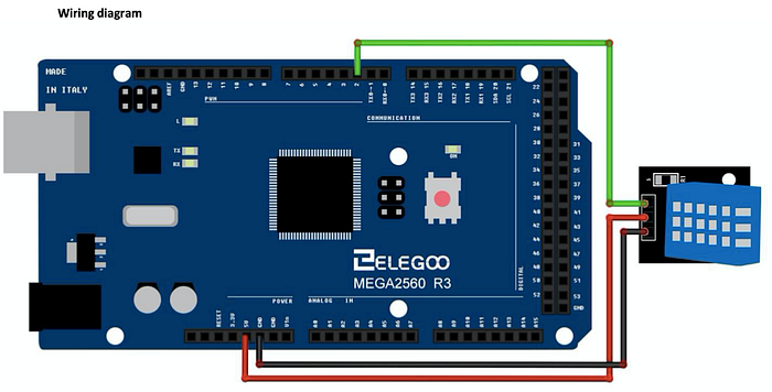

When wires are connected then we plug in the USB cable in the controller board and computer. Open Arduino software, remove all default code and paste in the following code from this link. Important note — if you have never used this sensor you may have to install the DHT library. You can find it on the elegoo home page under “THE MOST COMPLETE STARTER KIT TUTORIAL FOR MEGA 2560” or somewhere else. If you use a different temperature sensor that also should not be a problem, because we will need to collect temperature data and pass it into code. If everything is ok then send data to the controller board and in the serial monitor, you should get some temperature and humidity data.
The next part will be to connect the Bluetooth module. To make it more fun let’s also add Led light so we can receive data from Bluetooth and also send back — turn on and off led light. For this, we are going to use a breadboard to connect all. Open Arduino software and add code from this link. And here is the wiring diagram:
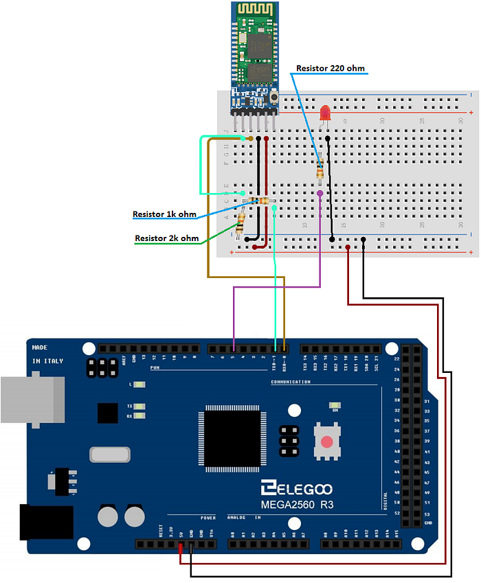
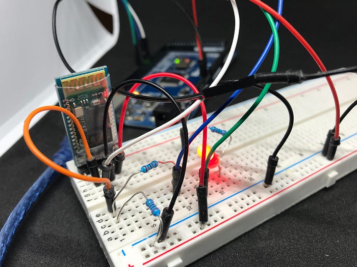
One quick note — if you are uploading code to your controller board and Arduino software is showing you some strange error, then unplug USB from the computer, disconnect 5V wire from your controller board, plug back USB in computer and then upload code. After the code is uploaded, remove again USB from the computer, plug 5V into the controller board, plug back in the computer and you should be good to go. I don’t know why, but sometimes this error occurs.
The next step is to download the app to your android device. There are a lot of apps, I downloaded “Bluetooth Terminal HC-05”. It’s quite heavy with ads, but it’s also free. When you open the app you can scan for nearby devices and if your Bluetooth module is blinking then it will appear in the list (probably with the name HC-05) and password to connect 0000 or 1234.
When you connect you will have this screen. At first, there will be no data in the black square. Now try in “Enter ASCII Command” enter number 1 and “Send ASCII”. Your LED should turn on and on-screen showing number “1” and text “On”. Then enter 0 to turn led off. You can long-press on buttons Btn1 and Btn2 to rename them On and Off and give values 1 and 0.
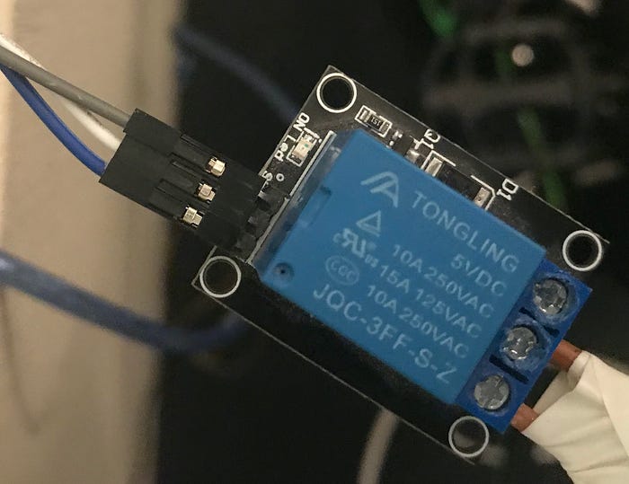
The last thing is the 5V relay. First, we need to attach it to an electrical cable. I had at home quite a thick cable and it’s not very flexible so it’s quite annoying to work with it but for prototyping, I will have to use it. Strip your wire in a place where you plan to attach relay. Cut one wire and attach both ends into relay one part in middle and other in NC (Normally closed) position. It does not make a big difference NC or NO but my code is written to NC position. Remember to be very careful with electricity — don’t leave open wires and don’t put 5V relay on a steel table or plate. When working with cable don’t forget to unplug it from electricity. Add three jumper wires to the 5V relay and let’s connect everything together.
To make it less complex and also we don't need it anymore — I removed Led light from the breadboard and all parts which were necessary for it. So final code you can find here. All temperature values are in celsius degrees, if you use different you will have to do little math. So important thing here — I don't know where you are and where you will test your device so I can not guess how high the temperature is at your place. You can change data to your specific needs in code line 46 where you will find “if(temperature > 28)”. In this case, the relay will change status when the temperature will be higher than 28 degrees C. If you want different results just change 28 or > to <. If your relay turns on when you need it to turn off and opposite, then you can change code on lines 48 (“digitalWrite(8, LOW);”) and 50 (“digitalWrite(8, HIGH);”). Change LOW to HIGH and HIGH to LOW. So this will be the end of part one.
And here is the final diagram.
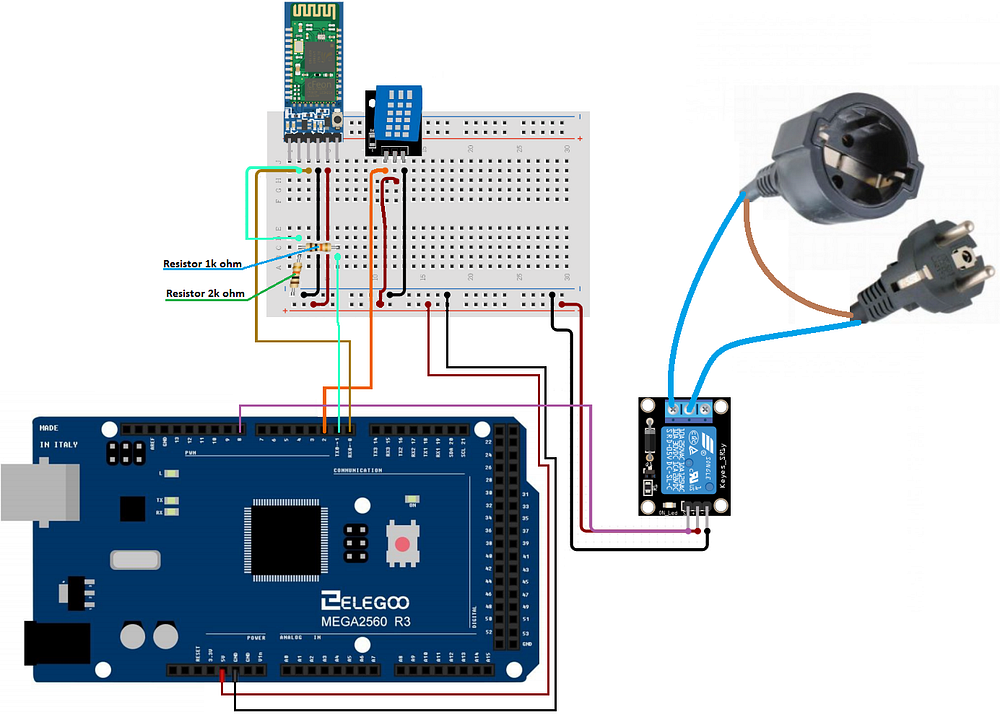
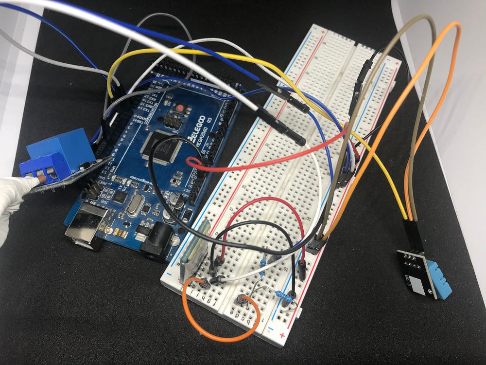
When everything is connected and the last code is uploaded to the controller you will be able to turn on and off relay from your android device (sending ASCII command 0 or 1). And also automatically change relay status depending on the temperature values you entered in the code.
If you are good with soldering then you can make it more stable with some prototyping board or stripboard. I'm will use perf board for this project, because you can cut it how large you need it. You can check the one I'm using in the affiliate link here.
End of part one…
